
As you’ll see in upcoming posts at work we make front panel stickers using polycarbonate overlays. So I thought I’d go through the process of cutting out / routing the label. It’s been a bit of a long route to perfect this process as really the labels should be laser cut as they are so thin it can be difficult on the cnc router.
1. CAD
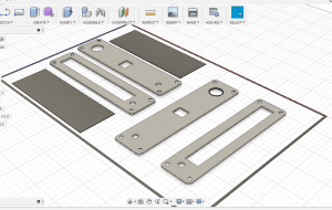
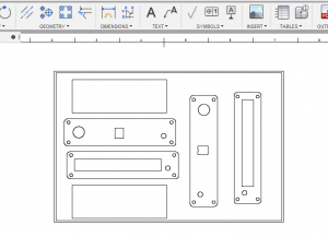
This stage may been obvious, you want to create a label from your front panel design. However, once you have your front panel in cad you’ll want to draw a box around your panel (10mm offset from you panel).
You can see in the example below, I drew a 3D box around my group of panels so that I would get the lines in the 2D drawing.
| 3D | 2D |
 |
 |
2. Export
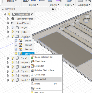
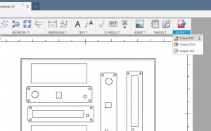
You now want to export a PDF of the 2D drawing and a DXF of the 3D layout.
| DXF | |
| Ensure in your 2D drawing you select a 1:1 drawing ratio.
|
 |
3. Graphic Design
You can now load the pdf drawing into your selected graphics editor. I’m using Photoshop as I know it quite well from my web design. However Illustrator, GIMP, Inkscape will be just as good if not better suited.
Once your PDF is loaded into your software, crop it down to the outside of the border line we added in stage 1. Now that’s done, design away!
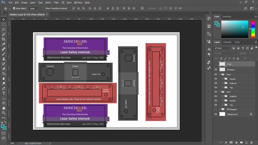
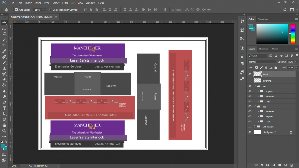
4. Get Ready to print
First we need to remove all lines from within the borders, as we don’t want black lines around our cut outs. As you can see I have two layers “Print” and “Drawing”. Drawing has all the guide lines to help in the design process; whereas print only has the board lines.
5. Make the labels
Part 1 discusses the methods of making the labels, in particular the method I use (lamination method).
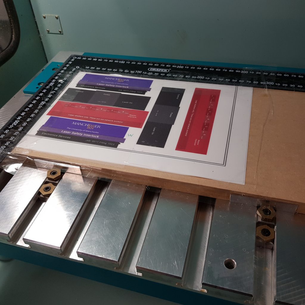
6. Aligning and Setup
This stage involves aligning the outer or inner guide line with a set square on a sacrificial piece of wood (mdf, plywood, softwood). Tape the label sheet to the square, the square to the sacrificial and the label to the sacrificial. Sellotape is all that is required as the cutting force is very small.
The square is used as the base board may not be square long the edges. It also allows for the A4 sticker to go underneath the square making it easier to align.
The base sacrificial board can then be clamped to the bed of your router any way you wish. Preferably the square would be at 0,0 however this is not 100% necessary so long as you know its coordinates.
7. Generate G-Code
Next load your dxf from before into you CAM program you used to generate your G-code. For front panels we just use the supplied software with our Boxford router. Its a combination of Techsoft and Boxford’s own in house software, however you could use any package you like for this. The type of CAM being used is only 2.5D so there are plenty of free solutions.
When generating your G-Code you can use the outer guide line as your zero coordinates.
All depth of cut should be 1mm if you are using my label system and routing method.
8. Router Setup
Below are some suggestions for setup
| Feed: 200 mm/min (Could be alot faster) | Speed: 13000rpm |
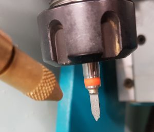
| Mist coolant on with water. Ensure a very light mist, turn down the air pressure to 2 bar’ish. See how the bit to the right has small balls of water building up, but not a stream.
Mist coolant stops the polycarbonate from building up around the bit. |
|
| Use a cnc router engraving bit | |
| Set up the engraving bit as a HSS straight cutter.
The width of the bit is 1mm upwards from the point end, in my case 0.7mm. |
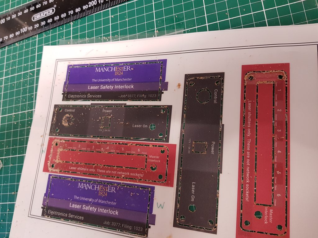
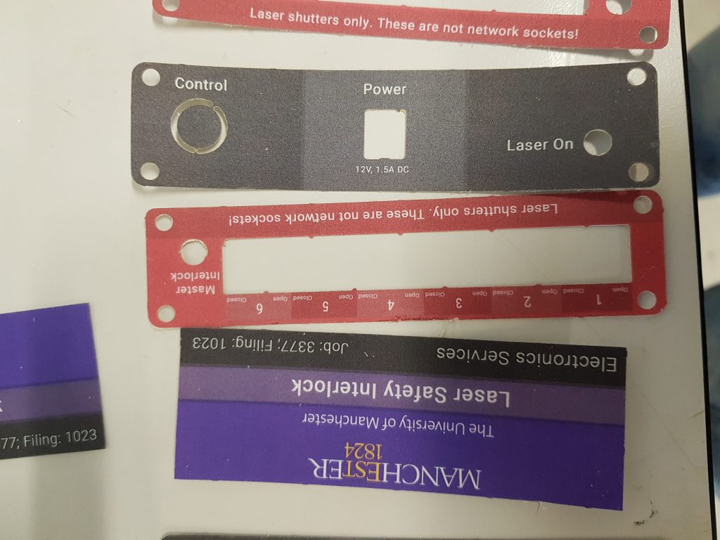
9. Clean up
If you have followed the above you should now have something like this below. Most of the debris you can see below is from the sacrificial mdf board. Cut the tabs holding the labels in and give the label a quick wipe. I find it easier and quicker when using tabs to cut them roughly and then give each side of the label a quick wet sand.
| Before Cleanup | After Cleanup |
 |
 |


