
With the development of QutiPi over the past 6 months on and off, I’ve started to design some standard hardware modules that fit in with the system.
One problem I had was how do you power down an embedded processor running an OS correctly. Most system with a micrcontroller just cut the supplies, however this isn’t safe for SoCs running an OS for multiple reasons.
- Data corruption: Everybody knows that when shutting down your computer you tell the operating system to shutdown, after which the OS takes a few moments to safely shut down. Unplugging the computer from the socket is somewhat unwise and this goes for embedded SoCs also. QutiPi runs a custom Linux distribution which means powering off by cutting the power could cause corruption of data.
- Application shutdown: A great side effect of powering down an OS correctly is that it first closes running programs. This means that the running programs can perform operations before the SoC is shutdown. This is great if you want to change the state of external hardware before the SoC is shutdown.
Solution LTC2953
We now know there are issues, so one solution is to use a push button on/off controller like the LTC2953. This IC comes with some nifty features such as:
- Under voltage: Shuts down the device when VCC drops below a set value (definable).
- Power failure: Alert the embedded device when VCC drops below a set value (definable).
- Voltage Monitor: Monitors a voltage and resets the embedded device when it drops below a set value (definable).
- Hard reset: If the device is not responding the user can hold down the button for a set amount of time to perform a hard reset.
- Switch debouncing: A simple critical feature is that button pushes have to be longer than a set value to result in an action.
- State sequencing: Most importantly the IC controls the progression of shutting the supplies to the embedded device. In summary, on power down the IC first requests the SoC to shut down, it waits, and once the SoC has shutdown the supplies are cut. On power up the device turns on the supplies and then expects a response from the SoC within 32mS otherwise the supplies are turned off.
Connections
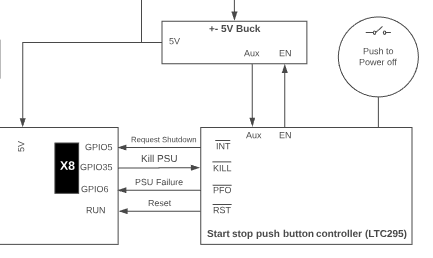
| To the right is a simple diagram of how the LTC2953 is connected to SoC, in this case the motherboard designed for QutiPi with the Raspberry Pi Compute Module 3.
The push button controller (see below) was designed to link up with DC/DC module I designed a while back; represented as +- Buck in the diagram. The EN input enables the two buck regulators. While the Aux output is an 12V 50mA supply, which powers external logic to control the DC/DC, in this case the LTC2953 board. It’s important that the GPIOs selected on the SoC have the correct logic states on boot up. For example, KILL is connect to GPIO_35 because the default state is high. |
 |
Schematic Design
The design of this board is pretty simple if you read the datasheet. However I’ll point out a few additional things I did:
|
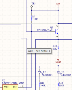
Buffer the EN signal The datasheet doesn’t seem to tell you the amount of current it can sink through EN. The DC/DC supply that this board is enabling has a resonantly low impedance EN input (to be addressed). Hence I buffer the signal with an emitter follower at around 1mA. |
 |
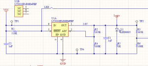
| Regulation for Output Logic
This board is going to be used with a variety of different microcontrollers / embedded processors. Hence I regulated the voltage used for the logic, so it can be set on build. |
 |
|
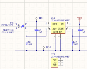
Push Button I designed the board to be panel mount hence there is a smd push button on one side. The push button I selected has a built in LED which I’m using to symbolise when the device is on. As VCC to the board can vary depending on the project it’s being used in. I’m using the LT3010 to set a defined current. It’s also nice to use as it has a shut down pin, which can be used with the KILL input on the LTC2953.
|
 |
Board Design
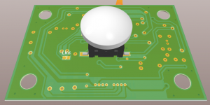
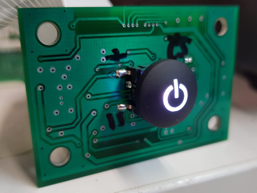
| Front
This side of the PCB has a SMD push button. |
 |
 |
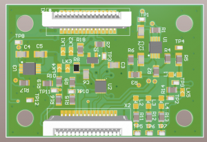
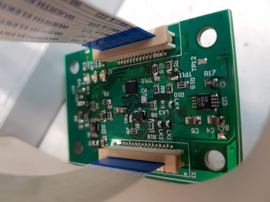
| Rear
This side contains all the components for the circuit. |
 |
 |
OS Integration
I’ve implemented the above into meta-qutipi which currently only supports the Compute Module 3 from Raspberry Pi. However it may well be very similar with other platforms that use Linux.
The quickest and easiest solution is to use the device tree if your version of the kernel supports such. You can find the list of supported dts in the raspberry pi kernel on there Github repo.
The two required overlays are gpio-shutdown and gpio-poweroff; gpio-shutdown is used to trigger the shut down event and gpio-poweroff is to set a gpio state once shutdown.
You can see the implementation of this in meta-qutipi .
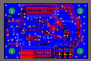
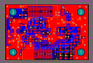
Images of PCB
 |
 |
Video
The below shows the LTC2953 in action. It’s attached to a DC/DC I designed awhile back and a prototype QutiPi board.


