
There are thousands of articles online about power factor correction. However i wanted to create a post summarizing the problem and a simple active solution.
What is it?
First lets look into the what “power factor” actually is. Power factor is a number which remains unit-less and generally speaking the perfect value is 1, we’ll get back to this later. Power factor only comes into play in AC circuits and can be measured at an equipment / board level or for an entire building.
Power factor explains the relation between “True Power” and “Apparent Power” within a system.
\( Power Factor =\frac{True Power (kW)}{Apparent Power (kVA)} \)This boils down to the difference between the amount of energy put into a system (apparent power) vs what is delivered to the load (true power, the usable stuff kind of). The additional energy put into the system that is not delivered to the load is lost as reactive power kVAr, this is energy we pay for but get nothing in return. We do need reactive power sometimes, for example, to generate a magnetic field in a motor.
\( Apparent Power = kW \times kVAr \)How is it represented?
Power factor can be calculated and drawn using a triangle. The below diagram shows if you increase the reactive power, the apparent power also increases. Basic trigonometry allows use to find a range of these values if we know two or more values.
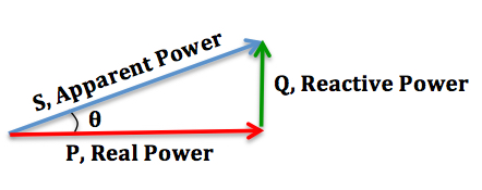
Property of https://en.wikipedia.org/wiki/Power_factor
Why its important?
Well for most house holds it is not, as energy companies only charge for the kWh used. However for commercial invoices companies will charged for everything broken down into kW, kWh, kVA and KVArh. This is down to the quantity of usage by commercial companies being far higher than that of a house hold. Energy supplies particularly dislike reactive power as it increases the current flow and increases the voltage drop in the grid; resulting in less capacity to serve other users on the grid, even to the point of causing failures due to excessive current. Due to the type of equipment used in industry they also tend to be high on reactive power.
Lets calculate the power usage of two motors, whereby one has a greater power factor:
| Motor 1 | Motor 2 | |
| Specification | Output Power: 1kW Power Factor: 0.7 Voltage Supply: 415 | Output Power: 1kW Power Factor: 0.98 Voltage Supply: 415 |
| Apparent Power | \(\frac{kW}{Power Factor} = \frac{1000}{0.7} = 1.42kW\) | \(\frac{kW}{Power Factor} = \frac{1000}{0.98} = 1.2kW\) |
| Reactive Power | \(\sqrt{kVA^2 – kW^2} = \sqrt{1.42^2 – 1^2}= 1 kVAr \) | \(\sqrt{kVA^2 – kW^2} = \sqrt{1.2^2 – 1^2}=0.66 kVA \) |
As you can see a motor with a higher power factor is more efficient, it requires less energy input for the same output power.
The Cause?
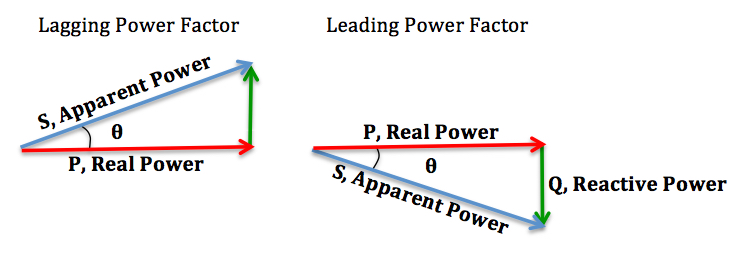
The main cause of poor power factors are inductive loads, more common in industry than consumers. When the load is purely resistive, the phase of both voltage and current and in sync, the same, hence a power factor of one. However with inductive and capacitve loads energy is stored temperately within electric or magnetic fields before being released back to the grid, hence altering the phase between voltage and current. With an inductive load the current to lag the voltage. This also means that a capacitive load causes current to lead voltage.
Simple Passive Fix
Now we know what effects the power factor, we know how to correct for it. We simply add capacitance to inductive circuits and inductors to capacitive circuits. For example, a motor is an inductive load hence we need to add capacitance. The capacitance will aid in correcting the power factor by providing a local source of reactive power for the inductive load, instead of sourcing this from the energy suppliers generators.
Simple right? Well… not too fast. When combining these reactive elements voltage fluctuation and noise can be generated to the extreme of creating resonance resulting in serious voltages spikes. As such we need to calculate our values carefully.
Active Fix
The reason i created this post is because i’m currently designing an active power factor correction PCB. I’m designing a 0-1000V 100mA & 0-24V 10A power supply unit and i want the equipment to have a good power factor. I’m doing the power factor correction actively as i want the power factor to be optimized across a range of loads.
I’ll be covering the design of this in part 2 coming soon.


